Sunday 1 October 2017

Islands in the Sky, Part Three - Living Space

Oh how I wish I could use my old but still trusty computer, I would be lacing this Blog with cgi renderings. For now I have to make do with showing some preparatory pencil sketches.

In this simple concept, chambers are like stretched out toruses and nested inside each other. This design imagines the habitat doubling as a space elevator counterweight, the tethers are the three thick lines along the centre. The overall design has to be for utility - in this case it's to have a uniform magnetic shield - and a cylinder is the easiest format for creating enclosures that will work for free-fall and rotational designs. I've drawn only one bulkhead, but I guess there could be as few or as many as one wants, and longitudinal and radial braces have to be incorporated to cope with potential bending forces and so on. These might conceivably form part of the exterior to maximise interior volume.

The exterior will not be smoothly cylindrical. Although possible, trapezoidal wedge shapes will have such subtle angles it would add complication to ensure that each and every brick is exactly the same. Better to have large flat sections that run the entire length, the exterior circumference having a polygonal aspect. At the vertices there would be transitioning bricks to make the angular change. As a result a construct could resemble the huge zeppelins of old. The end caps present the hardest problem, and are like sliced bagels. A similar tactic of flat and angular can be used.

Will a cylinder made from bricks of magnetic cast iron be strong enough to contain an atmosphere? Leaving aside leaking, since it would have a lining, the whole thing is held together by magnetism, then there is the secondary effect of cold-welding. A third mechanism is to hot weld all the joins, inside and out. Will this be strong enough? At a guess this early in my design work, I'd say yes. A fourth mechanism can be introduced, high tensile strength ribbon of the type eventually destined for lunar space elevators can be used to wrap up the exterior.

The longevity of a structure like this might conceivably run into many decades, perhaps centuries. The fixtures and fittings (life support and all that) should be designed and built for duration, some of this can be iron; refit and replacement is inevitable, but the iron hull will always be there, providing a haven within.

Monday 25 September 2017

Islands in the Sky, Part Two - Bring a Net

In the blog post Lunar Hammer Part One I wrote about Escape Velocity Angle Independence (EVAI henceforward), and now I am going to take that idea and run with it.

The equation in the Wiki entry implies that if a projectiles velocity is 0.99... of escape velocity, then it will fall back having reached a certain altitude. Let's say that altitude is in the region of L1. Let's put one of my theoretical Hammers directly underneath, then let's send a projectile up at a sliver under EV.

The flight path should be something like a very tall arc. The Moon is orbiting Earth so during the flight its position will change, and so will the location of L1. At the apex of its trajectory, the projectile will pass through the L1 region with diminishing vertical velocity but keeping it's horizontal (prograde) speed, so for a brief period it's moving parallel to the path of L1. At this point we intercept it with a net system. The problem, as far as I can tell so I'm happy to be corrected, is that there is going to be a speed differential, something like 150m/s if my simple sums are right.

As I write I am wondering if there is a solution where we can get an instantaneous relative velocity of zero, something like the inverse of a skyhook. If a projectile is angled to produce a retrograde flight path perhaps? This would almost certainly miss L1 proper I think. But maybe we can have a capture system that widely straddles the L1 region, extensions far apart to keep a stable network.

If we need a high speed capture system, we can refer to GK O'Neill/NASA studies of such things. As an alternative, I might propose a rotational system, with nets at the end of long rods. Linear velocity is translated into rotation and a braking system generates electricity from it.

Anyway, I'm out of my comfort zone now and I want to get on with writing about space stations made of iron.

EDIT:
I think the answer is L4 and L5?

Sunday 24 September 2017

Islands in the Sky, Part One - Recap

The main site has blog entries that really should go here, so without further ado...
(The formatting is all over the place and it's driving me nuts, please excuse any variations in text size and missing returns, I'm doing this on an old and crap public computer)

CAST IRON IN SPACE?
July 24th, 2017

Sounds ridiculous doesn't it. It's a steampunk fancy in the wrong place. But there is nothing wrong with the concept, it just jars with 21st century space tech as we know it - highly precise, over-engineered, perfection to 10 decimal places.

There are two basic strategies for cast iron architecture:

1 - magnetic iron is used to form open frames on which to attach stuff and simple walls/enclosing tubes to simply shield stuff; 2 - we push the envelope and create pressurized environments in which humans and other organic matter can live. 

The idea of building iron constructs that are habitable occurred not long after I had my eureka moment. Immediately I thought of magnetic toy construction, Geomag and Magnetix and the like, which permit geodesic-style frames, and then I considered, what if these frames were lined with plates? The plates could be welded, now there is an enclosure, a protective shell that could be combined with the developing inflatable module tech by Bigelow. Then I went a step further and wondered if the module could be omitted entirely and the enclosure simply lined with layers of space appropriate materials.

And so I swiftly went on with this enquiry - the main page shows a diagram of basic primitives, not included are wedge forms. With these now in mind, cylinders of any size could be built. The artistic rendering on the main page is simplistic, the reality would be a good deal more sophisticated. There is a substantial project here for an architect, or anyone with design skill for that matter. I will get to work on it properly when personal circumstances permit.


ABOUT THE HAMMERS 
July 31st, 2017
This post is to preempt inquiries about exactly what a Lunar Hammer is. The reason for the secrecy about how they function is because the modifications I have made to the basic design is potentially worth a patent application. I am hedging my bets for now. If you managed to make a correct educated guess, well done.
There is something worth mentioning - I don't want to patent it, and I don't want anyone else to patent it either. It should be totally outside intellectual exclusivity and free to adopt by any agency, persons, etc , etc. This my opinion on it. Having said that, however, if a company is to be started based on this tech, investors might insist on it and I'll just have to be practical about the matter.


ON THE BRICKS

August 2nd, 2017
Magnetic orientation is simple for disks and rings from the list of basic entities. A cube is straightforward as well, since any field axis is an affine transform of the others. It gets more complicated for a rectangular block (10 x 5 x 2.5 cm), here the field axis can take three orientations: lengthwise; width wise; height wise. 
Lengthwise spans distance and we get a wall 5cm for our template block. Widthwise presents the largest surface area; height-wise confers density of packing, the greatest contact area between the bricks. I guess the pattern we use depends on how thick we want the walls to be. I favour thickness. This would seem to present the highest density of magnetic field to the external environment. 

The above is early conjectures and I will be studying possible layouts and their implications for design.


ON WELDING IN SPACE
August 4th, 2017
First:- some clarifications for the main page (which I will not alter drastically for the time being). The LSE anchor-point I discovered is actually situated on the moons surface, according to the Wiki article. What I was referring to (in "What is the...?) is that location at the top of a cable (located at L1). 

Second:-  Cast iron construction can be done from Earth. The context in the main page is building stuff from the Moon, near the Moon, because that is how I arrived at the concept in the first place. 

On to welding in space. There is precious little written about the subject. Google it, and it's a 'void' subject. But it did bring my attention to cold welding last year. Nothing about welding with Sunlight using mirrors either. A YouTube video shows some bloke basically burning up a piece of metal with a parabolic mirror. To fine weld iron 'brick' ingots? A combination of mirrored sunlight to 'warm-up' an area to be melted and a finer application of heat by a high-power laser may be the optimal approach. 

The magnetism of my concept bricks raises interesting questions: molten iron, in a magnetic field, will want to follow that field, no?* On a north-south join, then fluid iron will stay where it is, generally, and some will creep into any cracks and spaces between the bricks contacting surface**. Then it cools down - in the presence of a field - and becomes magnetic again. 
* Correction: I've since learned that molten iron is amorphous and not magnetic.
** Whether it can move into cracks through capillary action is unknown.
On cold welding:- even before a molten welding technique is applied, the surface of every brick in contact with another could spontaneously join. Not completely, in a homogeneous sense, but at least where rough peaks, at the microscopic level, come into contact. Any molten iron that makes it way into the tiny spaces adjacent to a weld join might lead to further cold welding afterwards. 

Friday 22 September 2017

Lunar Hammer, Part Five - Applications

With the last few entries I have described the basics of the Hammer technology. Now to cover what it can be used for, and also present its potential for investment. Unfortunately we are stuck in a civilisation where nearly everything is defined in monetary terms.

Lunar Hammer
The Hammer on the Moon concept has to remain a very long term goal, but I'll summarise what it can be used for. The first and best use of Hammer is to kick stuff off the Moon, to shift resources over long distances. Set in an appropriate infrastructure, it can deliver magnetic cast iron for building large-scale structures that break the current paradigm for space habitats. This is what the Next Iron Age is all about, and I'll be going into more detail with a series of blogs about Islands in the Sky. Alternatively it can slug projectiles of other useful metals found on the Moon, a simple conveyor rather than the crux of a 3D printing system of a radical kind.

Skylance
On the Projects page at the main site, I sketch an idea called Project Skylance. Now that I have let the cat out the bag, I can describe it more generally. Essentially, Skylance could result if the Hammer system can be dialled up to 11 and more. In other words, try to achieve velocities well in excess of 2.4km/s. This is very much subject to what we can get from material science. Iron has a speed of sound over 5km/s, so the instantaneous force/velocity can approach this value until we get into a mechanical shock situation. But, working backwards, the Stack below needs to have suitable properties otherwise a Transmitter might/could/will disintegrate. Also, to get an artificial meteor, the projectile needs to burn up. This should be easier to achieve as launches will be more or less at sea-level.

Skylance is the first opportunity to gain investment for the Hammer system. The best way to use it is as a celestial work of art, perhaps located on the Greenwich Meridian. It's no good looking at it as some amped-up firework, it will be much too brief. Nevertheless, a sea-level-to-sky meteor trail will be a spectacular sight. The system will be small and portable, easily carried by a van, and I think it probable that a single technician could set it up. To end on a crazier note, I have imagined a 'meteor-in-a-bottle', wherein a thick glass tube runs up the inside of a tall building, and at the bottom there is a Hammer.

There is a serious science application to be gained from this venture. Meteors on demand, and at close proximity, means the trails can be studied in detail.


The Experimental Physics Experiment
In Part One in this series, I wrote a little about how Escape Velocity is somehow independent of the angle of launch of a projectile. This consequence still bothers me, and there is no experimental proof for this; it is a mathematical derivation. Since every means of escape from both Earth and Moon has only ever been achieved by rocket propulsion, it remains an abstract result. So how about an experiment to prove it? It needs to be conducted on the Moon, of course; we need a vacuum. A model scale Hammer can generate a range of velocities up to and including escape, and can project at angles. By far the trickiest part is the measurement, we have to be able to track a small projectile for tens-of-thousands of kilometres. We can limit this to a beginning and end. The beginning of a trajectory can be measured with radar and/or laser; the end can be predicted, and a satellite at a stable point, which obviously implies L1, can track with radar reflection the passing projectile. It will be travelling slowly by the time it reaches L1. Will it keep rising, or will it fall back to the Moon?


The Educational Science Display
I conducted a series of site visits at various public science venues in 2016. The Galilean Cannon has the makings for a good presensation of fundamental physics (arguably the Astroblaster already does this). In fact, it was while I was working on a sci-art installation that the project now titled Lunar Hammer came back to the fore in my mind, and I envisioned it in a similar way. So imagine, a small Hammer, consisting of maybe five or six elements in its Stack, launching a ball - at an angle - the entire length of the Turbine Hall at the Science Museum. Kids would probably care less about the science.


Tuesday 19 September 2017

Lunar Hammer, Part 4 - Origins, and 'Bit by Bit'.

I first came across the Galilean Cannon in 1993, at a science fair while at uni. It was a simple arrangement of three rubber balls. The idea stuck, but thinking back, it was the accidental find of a student assignment question, which I probably still have somewhere, that first triggered some desire to solve the problem. Not the mathematical solution of how many balls are necessary to achieve escape velocity on Earth, but to design a practical solution to do just that.

My notes and journals show that I was engaging with the problem, first in 1994, then coming back to it from late '95 into 1996. Quite a few sketches are undated, annoyingly, and by not having them I can't place them into context.

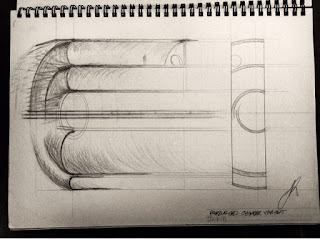
It looks like I left the problem alone until 2001. That's when the game changed. I was coming back to the problem frequently through the year, then in November that year I drew this:
I was certain I had arrived at the beginnings of a workable solution that could be applied to a stack of any size. Anyone seeing this will think, 'oh, that's obvious', but such thoughts only exist when the answer is right in front of you. When something doesn't exist, it is not 'obvious'. I took my work to UKC and the physicist who presented the demo I saw in '93. I was more than a bit nervous on the day, but he said, "yes, that would work", without hesitation.

I have felt a slightly surreal tone in my endeavours, realising only much later that I was tackling a problem, in isolation, that no one in history (as far as I could discover) has ever attacked in earnest. The first explorer into a new space of ideas. In retrospect, there is a good reason why my output that year, 2001, was different to what preceded it. In 1999 I started to develop my passion for art and design. As a teen I had the opportunity to study graphic design at college, but passed on it.


Bit by Bit
Cutting down each sphere is the first stage in a vitally important design methodology. The Hammer and the next few Transmitters are going to be massive lumps of elastic material. Creating these, and then shipping them to the Moon, is a fools errand. So, what can we do? We employ modular design concepts. The bulk of each object can be made up from layers (ideally manufactured on the Moon). The top and bottom presents a more difficult problem with much R&D needed, and I am leaving this to be addressed later in the event my project gets taken seriously.

Why does cutting down the balls make a difference? Think about the elastic deformation of a solid rubber ball when it bounces. The ball compresses along an axis passing through its centre of gravity and point of contact. This compression reduces as the deformation spreads through the whole ball, falling to zero at its circumference. Having practical experience with cutting up toy balls, I have seen the result of this phenomenon. For a test example I cut right through a ball clamped into a lathe, perpendicularly at about a third of its diameter. Since it needed to be secure, the ball was compressed, so I was cutting a straight line through a deformed object. When the pressure of clamping was released, the ball reformed, leaving a well defined 'hump'. I wasn't looking to achieve this as proof, it was actually incidental, but nonetheless I noted the outcome of the test, and got practical proof for my original assertion. In general, beyond the middle third, we can say "don't need that" and not lose much elastic potential.

This is my last post on the Hammer for now, next time I will be looking at its application. I'm sure some will consider this to be a load of tosh (or, to semi-quote Adam Rutherford, a steaming glob of weapons-grade fartgargle).

Thankfully for me, I will have any last laugh when I build the model that will project a ball-bearing at a kilometre a second.

Sunday 17 September 2017

Lunar Hammer, Part 3 - Lunar Hammer Described

In Part 2 I said I would describe what you see in the diagram, and why it looks the way it does.


Let's start with my nomenclature. At the top is the Projectile, the unit of stuff we want to get off the Moon. In the set position it sits on the Carrier. It deserves its own label because this could vary wildly in design, depending on what sort of shape gets sent up into cislunar space. The object at the base I call the Hammer, apposite considering this is where all the energy is coming from when it hits and bounces. Everything in between I term Transmitters, and the whole thing I call a Stack.

The diagram above embodies a pair of ideas I had way back in 2001: 1) we do not need complete spheres; 2) we can employ rails. There are further modifications to describe but these can wait for a future post.

The amount of volume removed from each part is 50%. An alternate configuration is to 'lathe' the spheres, leaving spherically capped cylinders, but this type of design will not interface as easily with rails. The first time I saw a complete render of the design above, I had a sensation of revelation. If Lunar Hammer is made real, it will, I believe, look similar to this. What is not shown is the replacement for the rubber mass taken away. This is denser material, sourced locally, to act as ballast and form the rail-stack interfacing mechanism.

When I first thought of rails I considered them acting as guides, but for the descent phase they are not  necessary, except for a variation that is only relevant to the Hammer. Where they come into play is post-impact, to keep the Stack neatly in place. With an angled variant, there will be reactive kicks that need absorbing by dampers. The thick lines in the diagram are for visibility and to mark the centres of each part of the Stack.

Friday 15 September 2017

Lunar Hammer, Part 2 - Lunar Hammer is...

...a heavily modified Galilean Cannon. Disappointed? Give it a chance, it can be extraordinarily useful. It may be a simple beast but it can be powerful, and it isn't limited to the vertical:

This configuration occurred to me thanks to an erroneous comment from a member of the BIS technical committee. With the revelations of the last post, I can have cake and eat it. It can work an angle, and is actually better suited to take this approach given the variation in size of each object in the stack that need to be accommodated by the rails. This can be seen in the concept diagram below:

The Hammer design shown here is at the top end of the size scale, based on launching a projectile 1kg in mass. If it's half a kilo, everything is halved. I will describe the relevant features in my next post, and why it looks the way it does.

The independence of Escape Velocity from angle of projection means that we can cap the velocity at 2.4km/s. The least known aspect of my research is the speed of force transmission up the stack. What will be the instantaneous velocity between the Carrier (the second element in the Stack) and the Projectile? It will be a fraction of the outgoing velocity, and it may or may not exceed the speed of sound in the rubber. If the superball rubber (by which I mean Wham-O's proprietary Superball formula from the 60's) has a typical s.o.s similar to a figure for a butadiene I found on the web, it could be around 1200m/s. This, at a guess, is already close to what we need, and I would think it possible to find a substitute material or a stiffer rubber formulation that is well in excess of this number.


Islands in the Sky, Part Three - Living Space

Oh how I wish I could use my old but still trusty computer, I would be lacing this Blog with cgi renderings. For now I have to make do with ...